

Discover defects in audio circuits injecting a signal step by step is an extremely useful technique, used by most technicians.
But for those who want a brief overview of this instrument, we can say that the signal gun is nothing more than a test oscillator which generates a rectangular signal, usually of 1 kHz or thereabouts, rich in harmonics.
Thus, this signal can be injected in both amplifier circuits or audio processors or RF to make its diagnosis, test or calibration.
The most common configuration of a gun signal is shown in Figure 1 consisting of an astable multivibrator with two transistors.
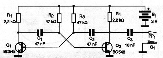
The signal of this circuit is applied to the inputs of the steps, making sure if there is the transition to the following steps or playing on a speaker, if it is an audio circuit.
At the point where the signal is injected and does not appear in the output we have the defective step.
Note the existence of an alligator clip to be connected to the ground point of the circuit being tested.
The probe is applied to the points where the signal must be injected.
In our case, instead of a transistor oscillator, we use an application that generates a fixed frequency signal (the reader can choose) and which makes it available in its audio outputs.
How it works
The output of the two cell phone audio channels is for low impedance headphones (32 Ω). Thus, when using the signals of these outputs we should have the utmost care not to put them in short accidentally, offering to the signal a low impedance and isolate them from the circuit continuous component.
This is done using a small additional circuit formed by only two components which we can build on a contact matrix or even on a terminal bridge (if the reader finds one).
The circuit consists of a resistor of 100 Ω which serves as a load to the headphone output of the channel used, and a 100 nF capacitor which couples the signal to the test circuit.
Assembly
In Figure 2 we have the complete circuit that has, besides the two indicated components a stereo plug, for the headphone output, using one of the channels, a probe and a claw.

In Figure 3 we have the assembly details, noting how the stereo P2 plug is connected to remove the signal to the circuit.

If the reader has the ability to weld the wires directly on the corresponding channels of the P3 plug can remove the adapter.
See the article CEL003E to identify the terminals.
The probe and the claw are used to access the circuit being tested.
The claw is connected at any point on earth.
In this circuit, the signal strength is adjusted on the cell phone volume control.
The Application
On Google Play there are many applications available which can be used to generate a fixed frequency audio signal.
We chose the High Frequency Sound whose screen is shown in Figure 4.

The frequency chosen in the screen example is 5 kHz, but for a gun in audio tests, the optimal frequency is 1 kHz.
Just pick and click on start and the signal is produced. If you remove the plug from the headphone jack, you will hear the signal from the speaker.
To use the gun look at one of our articles how to do it.


