
DC Motors
The simplest way to add motion to robots, mechatronics devices and other automation equipment is using DC motors. DC motors are cheap, small, efficient and can be found in a large range of sizes, shapes and powers.
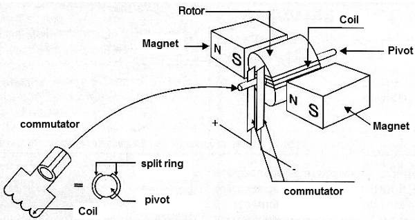
A conventional DC motor is formed by an arranjement of coils and magnets that creates motion for electric power. Figure 1 shows the typical construction of a small DC motor.
We can use these motors to move any mechanism directly or adding some gear device or tracks to change the speed or increase the power (see gearboxes in other articles in this site).
The basic properties of a DC motor that must be considered when using it in robotics or mechatronics project are:
Direction
When powered from a DC power supply (batery or other) the direction of the rotation of the shaft depends on the direction of the current flowing through it. Inverting the current we can invert the direction of the movement of any device coupled to a DC motor.
Speed
The speed or rpm (rotations per minute) depends on the voltage and the load.
We must consider two situations when using a DC motor: in the first case the motor operates without a load or a constant load. The speed will increase to a maximum that depends on the applied voltage.
In the second case, the motor operates with a variable load (the motor must power some kind of mechanism with forces that depend on the moment or the task. In this case, the speed depends on the load: more power = less speed.
Figure 2 shows the performance curves in the two cases.
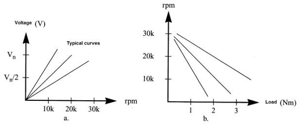
(a) Unloaded
(b) Variable load
Voltage
Small DC motors can be found in voltages ranging from 1,5 V to 48 V. The specified voltage indicates the nominal voltage or the voltage that applied to the motor makes it run in a normal condition (giving the maximum power and consuming the nominal current). In practice, the nominal voltage is important in a project as it indicates the maximum voltage that is recommended to apply to the motor when using it.
Current
The current of a motor, when powered with the nominal voltage depends on the load. The current increases with the load. It is important do not let the motor run with excessive loads that can stall it. In this stall condition the motor represents a short for the current and all the applied power is converted into heat. The motor can burn if let in this condition by long intervals of time.
Common DC motors can have operation currents in the range of 50 mA to more than 2 A.
Power
The power is given by the product of the voltage times the current. In projects involving robotis and mechatronics it is normal to indicate the amount of force that a motor can make by its torque.
As shown by the figure 3, the torque is the force released by the shaft and depends not only of the electric and mechanic characteristics of the motor but also of the shaft's diameter.
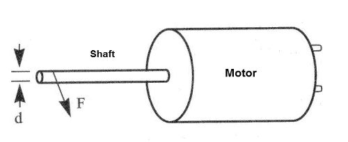
This specification is important as the force that a mechanism powered from a DC motor can source depends not only of the motor but also of the mechanism coupled to it.
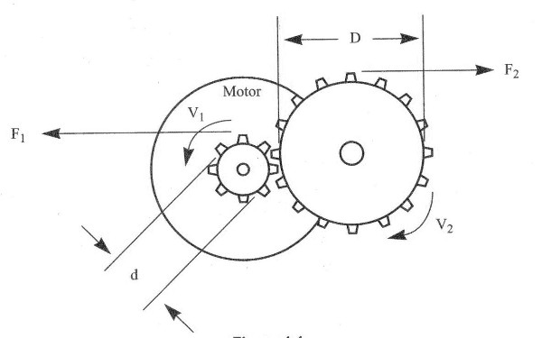
So, if gearboxes are added, as shown in figure (4.4) the speed can be decreased but the power can be increased in the same scale.
For instance, if a gearbox with ten times of the diameter of the shaft is coupled to a motor, the speed is reduced ten times, but the power is also increased by a ten times fator.
In robotics and mechatronics the use of gearboxes of all sizes and reduction ratios are common to match the characteristics of a determinated motor to a desired task.
So, when using a motor, is important to know the torque because starting from it and knowing the reduction rate of the mechanism to be moved we can easily find the final power that can be source by a system.
Speed
It is normal to source the speed of a DC motor in open condictions or no load condictions. The speeds can be in the range of 500 and 10,000 rpm according the type, size and other characteristics of a common DC motor. Remember that this speed will be reduced by a large factor when operating under loaded condictions.
Additional information
Small HE (High Efficience) and LE (Low Efficience) DC motors and gearboxes can be found in many dealers.
Many manufacturers and distributors have a large number of engine types in their line of products, with or without additional features such as reduction boxes or rotary axis modifiers, and power ratings in a wide range of values.
The designer can find the engine he/she wants, with or without additional mechanical resources, by consulting the internet.
Typical Characteristics
The speed (rpm) of a small DC motors depends on the current and so the load. Typical values are shown in the curves of figure 5.
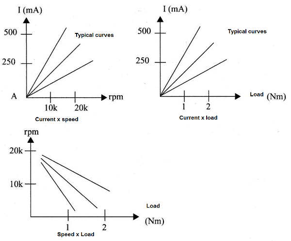
Observe that the speed rises when the ammount of force released by the motor is reduced and so the current drained by the unit.
Run the motor in an intermediate point of the characteristc is something that requires the use of electronic or mechanical controls.
PWM controls can be used to this task.
Protecting the Drive Circuit
DC motors are inductive loads and the action of the brushes can produce high voltage spikes in the controle circuit.
These spikes can both cause interference in other elements of the circuit or even cause damage in sensitive semiconductors as CMOS and FETs.
To avoid this problems some solutions can be adopted. They are shown in digure 6.
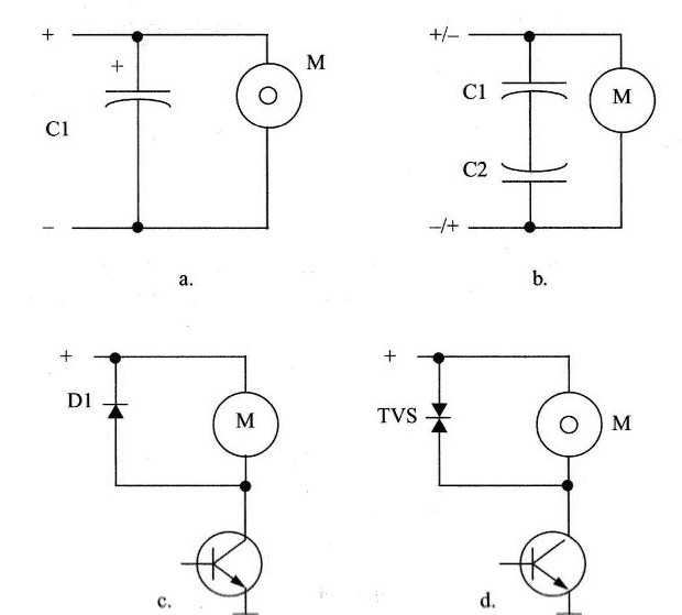
In (a) we show how an electrolytic capacitor (between 10 uF and 1,000 uF) can be wired in parallel with the motor.
If the motor runs in two directions so the voltage is reversed, two electrolytics must be conected as shown in (b). This confiiguration is equivalent to a non-polarized capacitor.
We remember that this protection is not recommended if the motor is controlled by semiconductors as bipolar transistors, power FETs, SCRs, etc. These components doesn't like capacitive loads.
If transistors or other semiconductors are used to controle the motors, diodes and TVSs must be used as shown by figures (c) and (d)


