

Motion Conversion
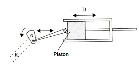
a) Rotary to longitudinal motion using a shaft and a piston
Figure 1 shows how a crank shaft and a piston can be used to convert rotary motion into longitudinal motion.
Formula
D = 2 x R (1)
Where: D is the displacement of the piston
R is te length of the crankshaft
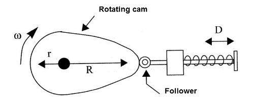
b) Cams used as a motion converter
Figure 2 gives na example how a rotating cam can be used to convert to produce longitudinal motion.
Formula
D = R - r (2)
Where: D is is the displacement of the pin
R and r are the radius of the cam
c) Cams used in complex rotary to longitudinal motion converters
Complex longitudinal motion can be obtained using rotating cams with programed formats as the one shown by figure 3.
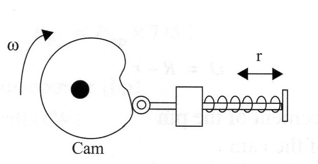
The moviment can be described by the equation of the shape of the cam.
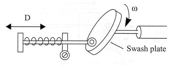
d) Rotary to linear motion conversion using a swash plate
A surface follower contacting a swash plane can be used to convert rotary into linear motion as shown by figure 4.
Acme screw and rider nut
This is an interesting technique to convert rotary motion into longitudinal motion.
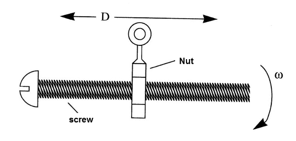
Formula
D = n x 2 x π x d (3)
Where: D is the total displacement of the nut i
n is the number of turns of the rotating screw
d is the step of the screw
e) Rack and Pinion
The rack and pinon combined can be used to convert bot rotary moviment into horizontal, vertical or inclined moviments that vice-versa. Figure 6 shows how the rack and pinion are used.
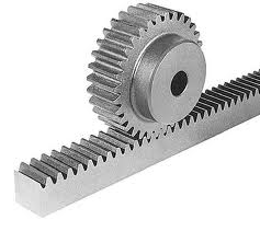
Formula
V = ω x R (4)
Where:
V is the tangential speed in
ω is the angular speed
R is the radius of the pinion
Obs: ω = 2 x π x f
Where: π = 3,14
ω = angular speed
f = the frequency or rotation per second
One-way Motion Controls
One-way motion controls are used to protect components, to limit power dissipation and for safety. Figure 7 shows some ways to implement one-way motion in mechatronics projects.
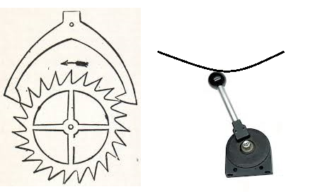
(a) toothed wheel and pawl
(b) braking pawl
Shaft Coupling
Figure 8 gives examples of shaft coupling techniques.
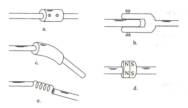
(a) Rigid coupler
(b) Flexible coupler - 1
(c) Flexible coupler with rubber tubing - 2
(d) Magnetic coupler
(e) Spring coupler


