Obs.: This article was published originally in Portuguese and translated by the author into English to be part of its book Electronic Projects from the Next Dimension. Other applications than the suggested in the text can be found by the readers.
The background noise picked up by MW and SW receivers is due to the internal components of the circuit (thermal noise) and atmospheric phenomena (static discharge) with a level defined by many factors such as solar activity, atmospheric level of static electricity, ambient temperature, and others.
This background noise can be amplified with the circuit we show here. This circuit produces a high level of noise, extending the frequency range from the audible range into the shortwave band, as high as 20 MHz, and it can be picked up by any receiver placed nearby.
Even in the VHF range, the noise can be picked up if the circuit is plugged directly to the antenna of a receiver. This allows the use of the circuit in experiments involving imaging with VHF TV.
Using the circuit is very simple: it is enough to tune any receiver (SW or MW) to a free point on the dial and place the noise generator near it. The noise will be transmitted and picked up by the receiver.
The noise generator is powerful enough to send the signals to receivers placed up to 20 cm away.
How It Works
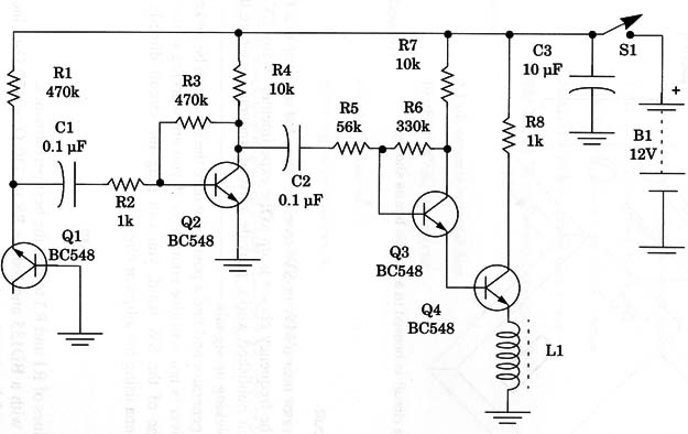
A white noise generator (one of the basic circuits described in this part) applies the signal to a power output stage using one transistor. The amplified signal is then applied to a ferrite core coil, which radiates it to receivers near the circuit.
As the load (ferrite coil) isn’t a tuned circuit, the produced signal spreads throughout the band with an intensity that decreases with the frequency. The circuit is useful from the MW band (550 kHz) up to the SW band (20 MHz or 15 meter band) when transmitting the signals.
But, if plugged directly to the antenna of a receiver, the signals can be tuned to frequencies up to 80 MHz.
The circuit can be powered using voltage sources from 9 to 12 V. In some cases, depending on the transistor used as noise source, the 9 V supply will not be enough to produce a good signal, and the voltage must be increased.
Assembly
Figure 1 shows the complete circuit of the noise generator.

The coil is formed by 40 to 100 turns of any enameled wire between 22 and 30 AWG, or even plastic-covered wire.
The core is a ferrite rod with a length ranging from 10 to 25 cm. The core can be any convenient diameter.
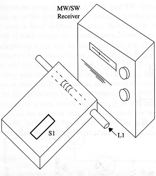
A plastic box can be used to house the circuit. The coil can be installed as shown in Fig. 2.

Dimensions of this plastic box are determined by the size of the cell holders. This figure also shows the circuit placement near a receiver when in operation.
If you intend to plug the circuit into a VHF receiver or TV set, a wire with an alligator clip can be connected to the collector of Q4. This clip is then attached to the antenna for transferring the noise.
Using the Circuit
Place the generator near a MW or SW receiver. Tune the receiver to a free point on the band. The frequency choice is up to the experimenter. Many EVP experimenters, in their published works, provide a list of frequencies where they were successful in picking up signals.
Turn on the generator and find a position where the noise can be picked up easily. If the receiver is not sensitive enough, or if you are working in the high-frequency extreme of the SW band, you can plug the circuit directly into the receiver’s antenna using the alligator clip.
Suggestions
Alter the values of R1 and R3 to find the best performance.
Replace Q4 with a BD135 and reduce R8 to 330 Q or 470 Q to increase the output power of the circuit.
Wire a variable capacitor (120 to 470 pF) in parallel with the coil to tune the noise.
Add a switch in series with a capacitor between 4,700 pF to 220 nF in the noise generator to produce pink noise. This circuit is placed between the base of Q1 and the ground.
Use this circuit to increase the noise in a TV screen when performing experiments with images.
Project
Semiconductors
Q1, Q2, Q3, Q4 - BC 548, 2N2222 or any general-purpose NPN silicon transistor
Resistors
R1, R3 - 470 k Ω, 1/8 W, 5%-yellow, Violet, yellow
R2, R8 -1k9, 1/8 W, 5%-brown, black, red
R4, R7 - 10 k Ω, 1/8 W, 5%-brown, black, orange
R5 - 56 k Ω9, 1/8 W, 5%-green, blue, orange
R6 - 330 k Ω, 1/8 W, 5%-orange, orange, yellow
Capacitors
C1, C2 - 0.1 µF, ceramic or metal film
C3 - 10 µF/ 16 WVdc, electrolytic
Miscellaneous
L1 - Ferrite coil (see text)
S1 - SPST, toggle or slide switch
B1 - 9 or 12 V battery, power supply or 8 AA cells (see text)
Printed circuit board, plastic box, cell holders (two for 4 AA types) or battery holder, plastic box ferrite core, AWG wire (see text), wires, solder, etc.


