

Uniform magnetic fields can be generated by a long straight coil of copper wire as shown by figure 1.
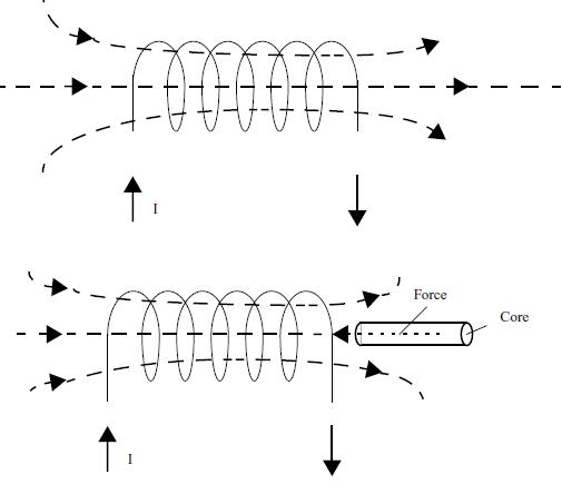
If a piece of iron is placed near the solenoid it is pulled by the magnetic forces generated by the solenoid releasing mechanical force.
The force pulling the core depends on several factors:
a) the current through the coil
b) the number of turns of the coil
c) the material of the core
d) the stroke
Common solenoids powered from 3 to 48 V DC supplies have currents in the range from 50 mA to 2 A. Some solenoids can release forces of several kilograms when activated. Solenoids can also be powered from AC supplies.
Types
Figure 2 shows some of the main types of solenoids.
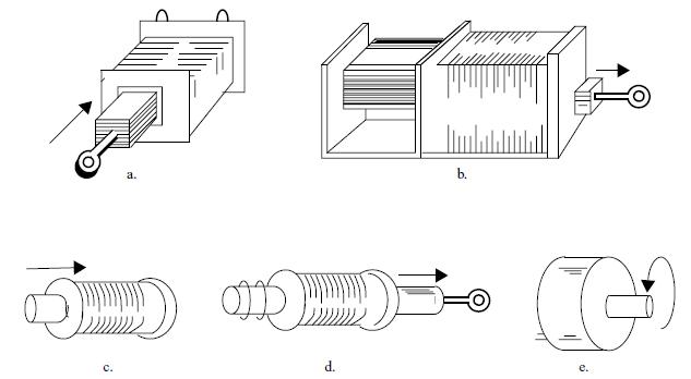
(a) Linear Laminated - pull
(b) Linear Laminated - push
(c) Linear Tubular - push
(d) Linear Tubular - pull
(e) Rotary
Using the Solenoid
Solenoids are used when is needed only a small push or pull acting on a piece accross a small distance as shown by figure 3.
It is enough to couple the solenoid to the piece where the force is needed considering the displacement of the core in each case.
Since there are practical applications for solenoids, they can be found in differents shapes and sizes.
Figure 4 shows some applications for the solenoids in mechatronics:
(a) Push action
(b) Pull action
(c) Using a lever
(d) Using a linear solenoid to obtain rotary motion
(e) Rotary solenoid
(f) Double action
(g) Lauching objects
Characteristics
The main specifications of a solenoid are:
a) The force/stroke released
The force released by the plunger of a solenoid is function of the applied voltage (and the current flowing through it). The nominal force is the force released when the nominal voltage is applied. This force is normally expressed in newtons (N) for linear solenoids and in terms of torque newin x meters (Nm) for rotary solenoids. Other factors that influence the solenoid force/troke relationship are the temperature and duty cycle.
b) The nominal voltage (Vn)
The voltage that may be applied to the coil of a solenoid to release the nominal force is the nominal voltage or operation voltage, Common types can have nominal voltage specifications between 3 and 48 volts.
c) Type of voltage
The solenoids can be powered from AC or DC sources. AC solenoids have different construction since they must include resources to damp the vibration caused by the changes in the direction of the current flowing through the coil winding.
d) The nominal current (In)
Is the current flowing through the coil when the nominal voltage is applied. This current chan vary between 100 mA to several amperes for common solenoids.
e) The nominal resistance (Rn)
Is the resistance of the coil winding. This resistance, with the voltage applied will determine the nominal current of a solenoid. For common types this resistance varies from fraction of ohm to some hundreds Ω.
f) Maximum dissipation power (Pn)
Heat is generated in the coil of a solenoid when a corrent flows through it. If a solenoid is overheated it can burn. One important specification of the solenoi is it maximum dissipation power. This power can range from some milliwatts to several watts. See in the next item how to calculate this power when it is not given by the manufacturer.
Other characteristics of importance in some applications is the mechanical life and force/stroke curves.
Formulas
The nominal voltage, nominal current and the nominal resistances are interdependent magnitudes and if two of them are know the third can be calculated using the Ohm's law. The next are useful formulas.
Note: these formulas and others can be found in the book Hamndbook for Formulas and Calculations by Newton C. Braga.
Formulas:
a) Determining the resistance when the voltage and current are known
R = V/I
b) Determining the current when voltage and resistance are known
I = V/R
c) Determining the voltage when the current and resistance are known
V = R x I
Where:
R is the resistance of the coil (Ω)
V is the nominal voltage (V)
I is the nominal current (A)
Formula:
a) Continuous use
The power dissipated by the coil of a solenoid when powered with the nominal voltage is calculated by the next formula:
P = V x I = R x I2 = V2/R
Where:
P is the power dissipated by the solenoid (W)
R is the resistance of the coil (Ω)
V is the nominal voltage (V)
I is the nominal current (A)
b) Pulsed
(Considering the duty cycle)
P = V x I x DT/100
Where:
P is the power dissipated by the solenoid (W)
R is the resistance of the coil (Ω)
V is the nominal voltage (V)
I is the nominal current (A)
DT - duty cycle (%)
In any application P must be lower than Pd (the maximum dissipation power) to not overheat the solenoid.
Obs: since in many applications the solenoid is activated only by a short time interval, discontinuing the power released, the maximum dissipation power will not be the limit.
Duty Cycle
The duty cycle of a solenoid is the ratio of time on to total cycle of time for solenoid operation. For the best operation the duty cycle should be ketp to a minimum.
Formula:
Duty Cycle:
DT = 100 x Ton/(Ton+Toff)
Where:
DT is the duty cycle in %
Ton is the time the solenoid is on
Toff is the time the solenoid is off
Obs: the duty cycle also determines the amount of power dissipated by the solenoid in an application.
Determining the Characteristics of a Solenoid
Solenoids can be made using common parts as card tubes, enameled wire and a screw as core as shown by figure 5.
The reader can calculate the number of turns needed to na applications but in general the differences between the theoretical calculations and the chareacteristics of the final device exist.
How to determine the characteristicis of a home made solenoid, a solenoid found in a surplus bin or taken from na appliance without any information about it?
a) Voltage
This is not na easy characteristc to determine. We can only suppose that a solenoid without any information about the operation voltage can be used in a task if it releases the necessary force without overheat.
The simplest way to test a solenoid, in this case, is to plug it to a variable power supply as shown by figure 6.
Rising the voltage we will observe if the force released is enough for the application we have in mind (we can measure this force) and at the same time monitor the temperature of the coil. The maximum voltage, for a safe operation, may not heat the coil to more than 50° C.
A curve force x voltage as shown by figure 7 can be traced from this experiment.
b) Current
The current in a DC powered solenoid depends on the applied voltage. Normally the indication of the current is given by the manufacturer but if it is necessary to determine it the circuit shown in figure 8 may be used.
The current through the coil can be read directly into the scale of the multimeter.
If the resistance and the nominal voltage of the coil of a solenoid is known the current can be calculated using the Ohm's Law:
Formula
I = V/R
Where:
I is the nominal current of the solenoid - or the current under certain voltage (A) in a specified application.
V is the voltage applied to the coil (V)
R is the nominal resistance of the coil (Ω)
c) Force
The force released by a solenoid can be measured using a dynamometer. Figure 9 shows three processes suitable for determine the force released by a solenoid.
(a) Using a dynamometer
(b) Using a common balance
(c) Using known weights
It's important to observe that the lever when using a spring dynamometer is need to increase the displacement since the indication of force depends on this displacement.


