

If the reader is lucky, you may find an old amplifier with EL84 valves at the output in some repair shop or scraps, and in this case, the use of the transformer, if it is good, can be done. Test the continuity of the windings for this and see if there is no short between these windings.
The modern touch, which this amplifier has, is only in the power supply, which replaces the old full-wave rectifier valves like the 6X4 by modern silicon diodes which cost less than 1/10 of the price.
The characteristics of this amplifier are:
Frequency range: 10 to 12 000 Hz
Distortion (15 W): less than 1%
Output Power: 15 W
Supply voltage: 110 / 220V
We also note that the output transformer must be of the ultra-linear type with a primary inductance of 40 H at 10 x 60 Hz.
Normally in this type of circuit, the secondary of the output transformer is equipped with sockets, which allow the connection of speakers of diverse impedances.
FUNCTIONING
The audio signal is taken to a dual 12AX7 triode, which has dual function.
Half of this valve is used in the pre-amplification of the signal, while the other half does the phase inversion. We then have signals with opposite phases, which are taken via C2 and via C3 directly to the control grids of power pentodes type EL84.
The suppressor grid is maintained at a high potential, thanks to the + B supply of a transformer socket.
The polarization of the control grids of the EL84 in push-pull is given by the resistors R6 and R7. See then that each valve amplifies half of the signal cycle, which then gather at the primary of the transformer to result in the complete signal at the secondary.
The resistor R10 in conjunction with C4 biases the valve cathodes together.
ASSEMBLY
We begin by providing readers with the schematic diagram of the power supply in Figure 1.

The diagram of a channel of the amplifier is shown in Figure 2.

This type of appliance must be built on an aluminum chassis. A layout for the arrangement of the components is given in Figure 3.
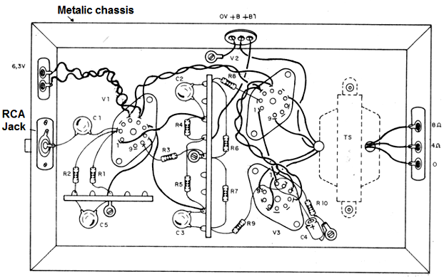
See that sockets are set in the chassis for the valves, as well as electrolytic filter capacitors of the threaded type oin the chassis, where its aluminum enclosure, when making contact with the chassis, is already the negative pole of the component.
The valves work very hot and this is normal, but good ventilation should be provided for the appliance, which should not be installed in an airtight box.
The resistors are ½ W unless otherwise indicated, and the electrolytic capacitors must have the voltages listed. The other capacitors are polyester with a working voltage of 250V or more.
Short or shielded wires are important for signal input.
USE
Turn the unit on and wait at least 30 seconds for the valves to heat up. Apply a signal to the input and check that it is playing on a speaker connected to the output.
Purchased the operation just use the device together with a good preamplifier. Even when operating at high voltages, a transistor pre-amplifier can be used as long as it has an independent source.
AMPLIFIER
VALVES
V1 - 12AX7 - double triode
V2, V3 - EL84 - power pentodes
RESISTORS
R1 - 22k (red, red, orange)
R2 - 1M2 (brown, red, green)
R3 - 68k (blue, gray, orange)
R4, R5, R6 and R7-100k (brown, black, yellow)
R8 and R9-1k (brown, black, red)
R10 - 150 ohms x10 W - wire
CAPACITORS
C1 - 220 nF polyester
C2, C3 and C5-100 nF polyester
C4 - 100 uF x 25V electrolytic
MISCELLANEOUS
TS - Push-Pull Transformer for EL84 Valve - 15 W
Metal chassis, valve sockets, terminal bridges, wires, etc.
SOURCE
SEMICONDUCTORS
D1 and D2 -1N4007 - silicon diodes
RESISTORS
R1 -100 ohms x 10 W - wire
R2-1 k x 5 W- wire
CAPACITORS
C1 - 32 uF x 450 V electrolytic
C2 - 32 uF x 450 V electrolytic
C3 - 80 uF x 450 V electrolytic
MISCELLANEOUS
T1 - Power transformer with a primary according to the network and a secondary of 250 + 250 V x 50 mA and 6.3 V x 5 A
Metal chassis, power cable, fuse holder, etc.
Note: C1 and C2 can be a single dual capacitor 32 + 32 uF x 450 V. The values ??of these filters are not critical, and up to 50% higher values ??may be used depending on the vendor availability.


