With only one integrated circuit and powered by a voltage of 4.5 V, it provides a signal of 2 V of amplitude, enough for most of the device tests.
By the characteristics of this test instrument, the readers can have a better idea of its versatility.
Characteristics:
Supply voltage: 4.5 V
Output range: 0 to 2 V
Frequency ranges:
20 to 200 Hz
200 to 2000 Hz
2000 at 20 000 Hz
20,000 to 200,000 Hz
Waveforms:
sinusoidal
triangular
rectangular
Adjustments:
symmetry and intensity
Number of integrated circuits: 1
The base of the circuit is an integrated 4049 CMOS which consists of 6 inverters that can be used as oscillators.
Readers may use this audio generator or functions for a variety of purposes.
How it works
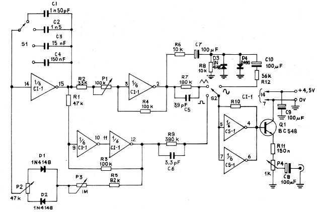
Four of the six inverters are used in the oscillator part, where the operating frequency is given by both the potentiometer position of 100 k in the feedback circuit and by the capacitor which is placed in the circuit by a 1-pole x 4-position switch.
With the choice of appropriate values we can scan the 4 tracks mentioned in the characteristics.
The 1M potentiometer works as the symmetry adjustment for the rectangular waveform mainly, so that its duration is equal to the separation.
The other two inverters are used to amplify the signal whose waveform is selected by a 1-pole x 3-position switch.
In addition to the amplification of these two inverters, we have a transistor which, in the common collector configuration, provides a potentiometer of 1k, a low impedance signal with good intensity. At this potentiometer is where we adjust the intensity of the output signal.
Assembly
The complete diagram of the device is shown in Figure 1.
As we use a 16-pin DIL CMOS integrated circuit, this assembly must be performed on a printed circuit board whose full size drawing is shown in Figure 2.
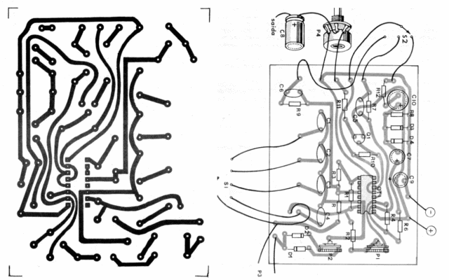
In this same figure, we have the connections of the external components which are the band switch, the frequency control and output potentiometers, and the power supply formed by 3 batteries connected in series.
Since a 3-cell holder is not easily found, we recommend that you use one of 4 batteries and place the fourth battery short, making use of a spent unit, as shown in Figure 3.
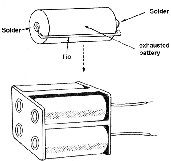
This fourth stack will act as a bridge simply to allow the support to be used.
Note the position of the CMOS integrated. This integrated is very sensitive to static discharges and should therefore be avoided its direct handling. It is only when the welding is done that the reader should remove it from the conductive sponge in which it has the spiked terminals.
The use of a socket ensures greater safety for this component.
The resistors can be 1/8 or 1/4W with the values ??listed in the material list.
The diodes are commonly used 1N4148 except the OA9O which is germanium.
When installing, be careful not to reverse diodes or electrolytic capacitors.
In Figure 4, we give a box suggestion, observing the use of an intensity scale for the output and a frequency scale.
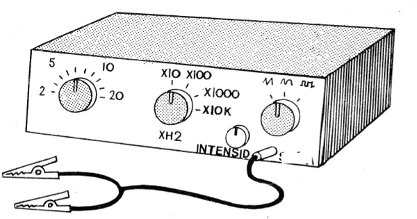
For the switch key it will be interesting to mark the waveforms obtained.
The potentiometers are linear and the electrolytic capacitors must have a working voltage of at least 6 V. The other capacitors can be both polyester and ceramic.
Testing and using the generator
Finishing the assembly check everything, and if you think the unit is in order, turn on the power.
The output may be coupled experimentally to the input of an amplifier, as shown in Figure 5.
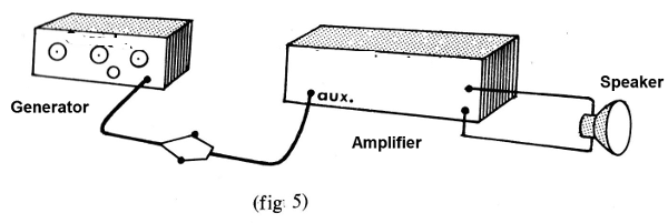
We use a cable with claws to facilitate the connections of the generator in the test apparatus.
Opening the amplifier volume, adjusting the volume (intensity) of the generator and selecting frequencies between 20 and 20,000 Hz should be reproduced in the loudspeaker.
Changing the waveform, we will notice this under the slight variation of the timbre.
If you can observe the waveforms on an oscilloscope, you can adjust the symmetry. In principle, simply leave the 47k potentiometer or trimpot in the middle position.
To use the device, keep in mind that its signal has an impedance of the order of 1 k and a maximum intensity of 0 to 2 V.
CI-1 - 4049 - CMOS integrated circuit
Q1 - BC-548 or equivalent - general purpose transistor
D1, D2, D3-1N4148 - silicon diodes
D4 - OA90 - germanium diode
P1 - 100 k - linear potentiometer
P2 - 47k - linear potentiometer
P3 - 1 M - linear potentiometer
P4 - 1 k - linear potentiometer
S1 - 1 pole x 4 positions rotary switch
S2 - 1 pole x 3 positions rotary switch
C1 - 150 pF - ceramic capacitor
C2. - 1n5 - ceramic capacitor
C3 - 15 nF - ceramic capacitor
C4 - 150 nF - ceramic capacitor
C5 - 3p9 - ceramic capacitor
C6 - 3p3 - Ceramic capacitor
C7, C8, C9, C10 - 100 uF .- electrolytic capacitors
R1 - 47 k x 1/8 W - resistor (yellow, violet, orange)
R2 - 33k x 1/8 W - resistor (orange, orange, orange)
R3 - R4 - R10 - 100 k x 1/8 W - resistors (brown, black, yellow)
R5 - 82k x 1/8 W - resistor (gray, red, orange)
R6 - 10k - 1/8 W - resistor (brown, black, orange)
R7 - 180 k x 1/8 W - resistor (brown, gray, yellow)
R8 - 10k x 1/8 W - resistor (brown, black, orange)
R9 - 39 k x 1/8 W - resistor (orange, white, yellow)
R12 - 56k x 1/8 W - resistor (green, blue, orange)
Miscellaneous: printed circuit board, output jack, wires, integrated stand, battery holder, mounting box, etc.


