Note: This article was originally written in Portuguese for the author's website in 2004, and later (2006) used in the book Bionics for The Evil Genius. Some changes to the original text were introduced.
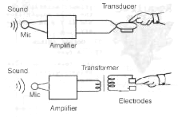
A common microphone picks up the sounds, amplifies them, and applies them to a transducer. Of course, other sound sources such as recorders, computers, and so on, can be used.
Two kinds of transducers can he used. The first is a vibrator that converts the sounds into mechanical vibrations that can be sensed by the fingers or other parts of the body. Research reveals that an interesting part of the body on which to place the electrodes, due to the sensitivity to vibrations, is the belly.
The other type of sensor is a high-voltage converter that produces an electric stimulus sent to electrodes that can be placed on any part of the body. Figure 1 shows these possibilities.
The simplest way to make a tactile hearing aid is to use a microphone, an amplifier, and a transducer, which is just what we are going to describe here.
Of course, many improvements can be made to facilitate communication between the hearing world and the deaf. Research is being made using signal processors and analog-to-digital converters to trans-form a sound signal to a form that can be easily recognized by the tactile senses. This includes filtering, the separation of the sound spectrum into bands, and even making changes in the wave shapes. This is an interesting bionics field to be investigated.
The evil genius, even if not deaf, can undertake this bionic tactile hearing project to achieve other purposes, as we will suggest in the next section.
The Projects in Bionics
The circuit described here is only a portion of a complete application. The evil genius can change the basic idea and work with other senses or even con-vert sounds to other kinds of signals, such as light or electric shock. Some ideas of applications are given in the following lines.
• The evil genius can use this circuit to communicate with friends using an invisible language of vibrations.
• Different sensations can be added to music reproduction so that you can hear through the belly (and other parts if you want).
• Help deaf people sense sounds and learn to speak (Many deaf people are also mute. They have not learned to speak because they cannot hear the sounds).
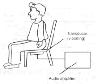
Figure 2 shows an interesting possibility for sound interfacing using vibrations, which is not recommended for practical purposes.
It is also possible to use the circuit in experiments with other living beings such as plants, mammals, and insects.
How the Circuit Works
The electronic part of the project is very simple. All we need is an electret microphone, an amplifier, and a transducer.
The amplifier can he the same one used in our first project and in the bionic ear, the unit using the LM386 integrated circuit (IC). It is an easy-to-find part and will have enough gain for the application we have in mind.
The transducer can be any electret microphone. This type of microphone has a field effect transistor (FET) inside, giving the device a high sensitivity. Finally, the transducer is the only part that the evil genius will have to mount with care.
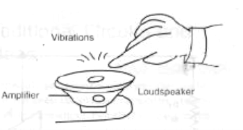
To convert the sounds into mechanical vibrations, even a small loudspeaker can he used. It is enough to touch the diaphragm to sense the vibrations, as shown by Figure 3, but details of another transducer will be given later.
The other transducer is a transformer that generates high voltage from the audio signals in the output of the amplifier. Applied to electrodes, the high-voltage signal can he sensed as a light shock in the finger or other places. An amplitude adjuster is also added to control the level of the stimulus, according to the place where the electrodes are used.
How to Build
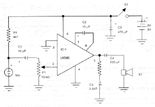
The circuit can use the same printed circuit board (PCB) described in the electric fish and bionic ear projects. Figure 5 shows how to connect the microphone and the transducer.
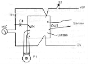
The power supply consists of four AA cells installed in a holder. When mounting, observe the position of the polarized components, such as the electrolytic capacitors, IC, and power supply. The electret microphone is also a polarized component.
If the wire that connects this component to the circuit is long, a shielded cable must he used. The screen must he connected to the 0-volt line or ground line of the circuit.
The Transducers
The simplest transducer is a small plastic loudspeaker placed on a base, and you must touch the cone to sense the vibrations. Another transducer is shown in Figure 6.
The coil is formed by 200 to 500 turns of 28 to 32 AWG wire on a small screw. The diaphragm is a plate made of iron, steel, or another magnetic metal.
The distance between the plate and the magnet is kept as low as possible to transfer the vibrations, which can he sensed when the fingers are placed on the sensor.
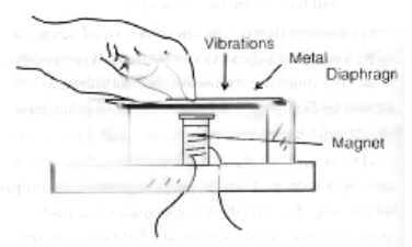
This sensor and the loudspeaker can be used to transfer the vibrations to other parts of the body, as suggested at the beginning of this project.
The electric transducer is a transformer with a 117-volt or other high-voltage primary and a 6-volt secondary with currents between 150 and 300 milliamps. As shown in Figure 7, the subject must place his or her fingers on the electrodes and adjust P2 to the ideal electric stimulus from the sounds picked up by the microphone.
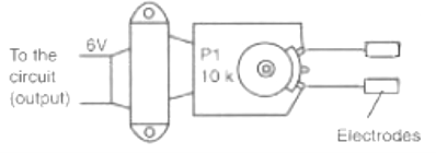
Testing and Using
Place the cells in the holder and turn on the power supply, closing S1. Then open P1 and P2. Place your fingers on the sensor and, when speaking near the microphone, the vibrations will be sensed.
Parts List
Required Parts
IC-1: L1386 (any suffix) integrated circuit
P1, P2: 10 kΩ log potentiometer
R1: 4.7 kΩ x 1/8 W resistor, yellow, violet, red
R2: 10 Ω x 1/8 W resistor, brown, black, black
C1, C2: 10 µF x 12 V electrolytic capacitor
C3: 0.047 µF ceramic or polyester capacitor
C4: 220 µF x 12 V electrolytic capacitor
C5: 470 µF x 12 V electrolytic capacitor Transducer (see text)
S1: On/off switch
B1: Four 6 V AA cells
Other: PCB, material for the transducer, cell holder, plastic box, wires, solder, etc.
Additional Circuits and Ideas
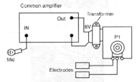
In principle, any common audio amplifier can be used to transfer the vibrations sensed by a microphone to a transducer. Two ideas are given in this section.
Circuit Using a Common Audio Amplifier
Figure 8 shows how to use a common audio amplifier to convert sounds into vibrations or electric signals. Audio amplifiers with power outputs from 1 to 50 watts can be used.
When using a high-voltage transformer, the evil genius must be careful to not use all the power pro-vided by the high-power amplifier (more than 10 watts). This can cause severe shocks or burn the transformer. Slowly open the volume control to reach the ideal point for the stimulus of the subject.
Other Circuits Using the TDR7052
Figure 9 shows how to use another IC as an audio amplifier in the experiments described here.
This amplifier can produce more than 100 megawatts to a small loudspeaker or even a trans-former, providing vibrations or electric stimulus for a subject.
Upgrading the Project
Deaf people, as well as the blind, can develop an acute tactile sense because in most ca!4s this sense replaces the one that is missing. Experiments can reveal the ideal stimulus for transferring the correct sensation of sounds to a deaf person. This experiment can include the use of filters or tone controls, or even frequency converters. The curious evil genius can discover many interesting things when developing a communication system using tac-tile vibrations.


