Living beings, including ourselves, produce electrical signals of various kinds. These signals can be used for the most diverse purposes, from checking our health or the health of an animal or plant to being used as a control device, e.g., in wearables and other applications.
In Figure 1, we have an example of electrical signals used in medicine.
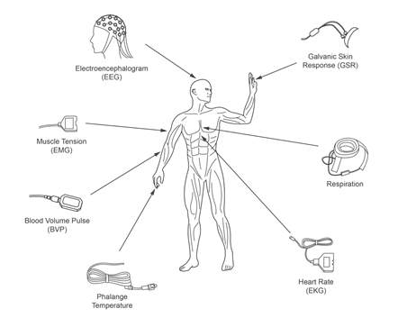
Although some are not electrical, we are particularly interested in the problems when working with these signals.
The signals are different but have a lot in common, which should be analyzed by any equipment designer who wishes to work with them.
The first problem that comes up when working with these signals is that they have extremely low intensity. These are signals that start from a few microvolts reaching at most a few tens of millivolts, as in the case of a neuron.
But it is not just the voltage that can make it challenging to capture the signal for use on an electronic device.
First, these signals are of very low power. The source has a very high internal resistance, which means that any measurement circuit (sensor) easily overloads the signal source, preventing or affecting the voltage reading.
Biopotential sensor circuits must have very high input impedances. It is expected that, in practical circuits, they are of the order of megohms or even gigaohms.
With a very high input resistance, we have one of the biggest problems in capturing: the sensor circuit can easily pick up noise.
In this category, we include electrocardiographs (ECG), electroencephalographs (EEG), electromyographs (EMG) and others that often need to be installed in grounded and shielded rooms to avoid capturing noise from the power grid or other nearby sources.
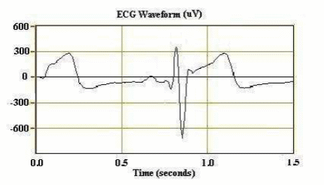
In Figure 3, we have an example of the biopotential used in an electroencephalogram.
Finally, we have the problem that arises from the fact that the signal sources are electrochemical.
The contact of electrodes with human skin, with any part of living tissue, with plants or animals is responsible for a phenomenon called galvanism. Formerly attributed to animal electricity, galvanism causes an electrochemical reaction on the electrodes used to capture the signal and on the living tissue itself.
In the case of the electrode, this action can cause its corrosion, making it unusable in a short time, and in the case of living tissue, it can even cause its death. The cells on which the electrode is fixed can die.
This requires special techniques to reliably capture the signal without affecting the electrodes and the living tissue and, furthermore, without affecting the signal.
The solutions
For designers of electronic circuits that operate with biopotentials, what happens with the signals and their processing is essential.
Thus, the most used circuit in the coupling of sensors to the processing circuit is the instrumentation amplifier, as shown in Figure 4. We have hundreds of such circuits in our "circuit bank" section, from older traditional operational amplifiers to modern types of ultra-low consumption and operating at very low voltages.
We can generally analyze this circuit as follows: at the input stage, we have two operational amplifiers whose gain is determined by resistors R1 and R2. This circuit must be configured to have a very high input impedance and operate in differential mode, with the floating inputs so that the circuit measures the voltage between them (E1 and E2). Input E3 serves as a reference or ground.
An important feature that this circuit must present is a very high common-mode rejection (CMRR). Common-mode rejection is the circuit's ability to not output (0V) when the input voltage at E1 is equal to E2. In practice, due to differences in the characteristics of the components, there is always an amplification difference that leads to the production of a signal when there should not be (E1 = E2).
It also means that the components used (resistors) must have a very low tolerance (1% and less) so that this does not affect the characteristics of the circuit.
The second stage presents an additional gain from the relationship between R4 and R3 (-R4/R3). Finally, we have at the output a stage that provides the signal amplification with low impedance output. C2 capacitor, together with R7, determines the high frequencies' cut-off.
Note that biosignals are usually of very low frequency, typically less than 100 Hz. The clipping of interfering signals that can arise in the circuit (induced RF, for example) must be eliminated.
In Figure 4, we have how such signals can be affected by the noise induced by an electric power transmission line.
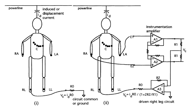
Note that the main enemy of these circuits is the signal or rumble induced by the electric power transmission line.
We are initially dealing with the possibility of the signals being picked up by the organism under analysis. Still, if there is no way to avoid it (we will analyze the capture by the circuit and sensor cables later), a solution would be to provide the input stages with filters.
There are many possibilities that the readers can find in our practical circuits in the "Circuit Bank" section.
For example, in Figure 5(a), we use capacitors in a low-pass filter configuration, and 5(b), a double-reject filter. The first cuts the high frequencies, and the second is tuned to the network frequency.
Another way to cancel any noise captured is with the use of bridges. These bridges can work with more than one electrode and thus cancel out noises that are eventually common.
In Figure 6, we have an example of bridge sensors.
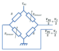
In this type of bridge, any noises that appear simultaneously in both sensors are cancelled.
Layout
Long tracks act as antennas, resistors and inductors. Nearby tracks act as capacitors.
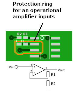
In a circuit with very high input impedance and high gain, noise in a parasitic way can drastically compromise the operation. Thus, in addition to the shortening of the sensitive tracks, we also have to consider the cases in which they act as antennas in capturing signals.
A typical procedure that must be considered is the so-called "guard ring" or ring of protection or shield that involves the inputs of an operational amplifier. In Figure 7, we have its use.
Grounding in areas involving sensitive circuits are also essential to avoid capturing noise that can affect the operation of the circuit.
Sensors and Cables
Appropriate sensors and topologies must be used for each type of signal, not to mention the need for special care with the cables.
So we have different types of sensors that must take galvanism into account. As explained in MA134, Galvanism is the electrochemical action on electrodes that contact a living or chemically active substance.
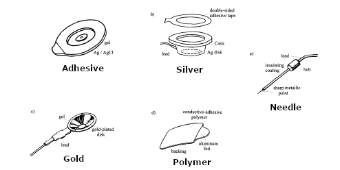
So, first of all, we have silver and silver chloride electrodes, which have excellent conductivity and which are connected to the human body, for example, through a gel.
Then we have golden electrodes that, in addition to their excellent conductivity, can be reused. These electrodes are found in ECG.
Another type of electrode for applications in the measurement of biopotentials is the conductive polymer electrode, which consists of adhesive material and its conductive properties.
Metal or carbon electrodes are found in less critical applications because of their low cost.
Finally, we have electrodes in the form of glass needles that are invasive as they need to penetrate living tissue. These electrodes are used when biopotentials are measured directly in an internal organ, such as in muscles.
In Figure 8, we have examples of some of the types of electrodes that we are dealing with.
And, to finish, we have the cables that must be shielded with the shields (meshes) connected carefully in points of the circuit that avoid the appearance of any voltage.
Conclusion
As we work with extremely weak electric signals with an intensity of microvolts or millivolts, the possibility of capturing noise is enormous, spoiling the readings.
Proper procedures are essential to avoid any problem that could affect the reading of an electric signal.


