

The working principle of standard fixed capacitors is well known to everyone who studies electronics. Two conductive plates or armatures are assembled in such a way as to have an insulator between them, called a dielectric, as shown in Figure 1.

The capacitance obtained will depend on the area of the armatures, the dielectric's nature (material), and the gap that will separate the armatures.
Thus, in a structure like this, we have a fixed capacitance that is determined by the factors analysed.
Of course, we can have other ways to assemble the capacitor. The armatures and the dielectric do not need to be flat, as in the case of the capacitor we saw, called the "flat capacitor". They can be assembled with flexible materials and coiled, as in the tubular capacitors, shown in Figure 2.

We can even have the stacking of flat structures that would have their capacitances added together, as in modern MLCC capacitors (Multilayer Ceramic Capacitor), shown in Figure 3.

However, there are applications where it is necessary to vary the capacitance of a capacitor. For example, in a tuned circuit where we have a coil and a capacitor in parallel, as shown in Figure 4, it is much simpler to change the capacitance than the inductance if we want to change its resonant frequency.

Thus, an actual application for a capacitor that can vary its capacitance would be in a tuning circuit like the one shown earlier. That has been the main application for this type of component.
How to get such a component? A capacitor that, through external action, can change its capacitance?
We can obtain such a component in several ways. We can change the distance that separates the plates. We can move a dielectric between two plates or move the plates so that the effective area changes.
We will analyse this last technique, as it is the most used in most variable capacitors nowadays.
As shown in Figure 5, the capacitance we get from two plates separated by a fixed distance depends on the surface they meet. We call it effective area or effective surface (overlap).
So, if we move one of the plates laterally, keeping the distance, the effective surface changes, decreasing as it decreases, and thus, we change the achieved capacitance.

In practice, one way to achieve an efficient arrangement for this component is to have one or more fixed plates and one or more movable plates.
Note that it is crucial to have plate formats that, when rotating, can linearly vary the obtained capacitance. The reason is that the resonant frequency of an LC circuit needs to change to get a frequency coverage that is easy to predict.
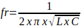
Remember that the resonant frequency of the LC circuit is given by:
Thus, in a tuning circuit from 550 to 1600 kHz, we have a non-linear frequency variation, with greater separation at the lower end and less separation at the upper end, as shown in Figure 6.

That is due to the geometry of the variable capacitors used.
Figure 7 shows a traditional way to build this type of capacitor, as found in old radios.

In this type of assembly, we have a set of fixed plates and a set of plates that move, penetrating (without touching) the set of fixed plates. In figure 8, we have the operation of the capacitor in the position of minimum capacitance (a), intermediate capacitance (b) and maximum capacitance (c).

We then find in much older equipment, mainly tubes, variable capacitors called "one-section" that have the symbol and aspect shown in Figure 9.

Typical capacitances of these capacitors ranged from a few dozen of picofarads to 410 pF, which was a common value for AM radios.
They were specified by maximum capacitance, that is, "all closed". The minimum capacitance was not zero, as there is always a residual capacitance when the plates are open.
The separation between the plates was an essential factor to be considered when using this type of component.
The tube circuits worked with high voltages. Very close plates meant the possibility of sparks flying. Thus, it was possible to obtain high voltage capacitors with greater separation between the plates for high voltage circuits, such as transmitters, as shown in Figure 10.

Going further, we would eventually find two or more resonant circuits that should work together in radio receivers. That is, their frequencies should be varied simultaneously. That occurred in receivers with tuned direct steps and superheterodyne receivers.
There was a variable capacitor of double or triple tuning for these devices, as shown in Figure 11.

Even today, you can get this type of capacitor and use it in your projects, of course, minding to test them.
As we can see from the figure, there is a terminal common to all three sections connected to the enclosure, thus making contact with the shaft and the moving plates.
That can be considered the component's ground. See the terminal at A in Figure 9. On the other hand, each terminal B is connected to a section of the component.
To test, use the multimeter on a low resistance scale. Connect one end to A and the other to B of each section to be tested.
By rotating the variable axis, the resistance must be infinite along the entire path. If there is a jump in the multimeter needle (analogue) indicating zero at any point, it is because there is a short circuit, as shown in figure 10.

That could mean a bent plate, some metal residue between them, or misalignment. The variable capacitors have a plate alignment screw, as shown in Figure 13.

Skilled makers can straighten the plates or carefully remove plates, changing the capacitance of the component.
Currently, mechanical variable capacitors are compactly constructed with plastic plates in various configurations, such as those used in transistor radios and other applications, shown in Figure 14.

The working principle is the same. In the figure, we have the common terminal B and the terminals A and C for two sets of plates. We can have quad types for AM and FM receivers, for example, with four sets of plates and six terminals, as shown in Figure 15.

For such capacitors, we must consider that the capacitance of the variables on one side (AM) is greater than that on the other side (FM). One way to distinguish them is to use a capacitance meter.


